Category: Uncategorized
Port Security

Switch port security monitors a port to restrict the number of MAC addresses associated with that port in the Layer 2 switching table. It can also enforce a restriction for only certain MAC addresses to be reachable out the port.
Instead of automatically adding a Layer 2 switching table entry for the source MAC and port number, now the switch considers the port security configuration and checks whether it allows that entry or not.
We implement the port-security to avoid MAC flooding & MAC-address spoofing attacks.
MAC flooding
Attacker connected to the switch port will generate & send thousands of frames with different source MAC addresses.
Total MAC-address space available in a switch is 6003, if the whole MAC-address table is filled then the switch will times out older entries.
If the switch receives frames destined for those MACs that are no longer in the table, the switch will do the unicast flooding(floods the frames out all ports).
This attack can be launched for the malicious purpose of collecting a broad sample of traffic or as a denial of service (DoS) attack.
so with the port-security we can limit the maximum number of MAC-address that can be learned on a port.

MAC-address spoofing
An attacker could also claim to be the same MAC address as a legitimate user by simply sending a frame with that same MAC address. As a result, the switch would update its switching table and send frames to the attacker.
So With port-security you can bind MAC-address on a port, so that you can allow only those MAC addresses on the switchport to access the network. Even though it is not secure, because we can change the MAC-address of the PC.
Maximum number of MAC-address that can be binded with the port are 1 by default. But we can increase this value to allow more users to access.
If a violations occurred then by default port-security puts the port into Error-disable state.

- There are two types of aging for MAC-addresses:
- Absolute aging:
- Means it delete the MAC addresses from the Port-address table after a certain period of time, even it don’t care that the MAC-address is active or not.
- Inactivity aging:
- If the MAC-address is not active for certain period of time, then it will remove from the Port-address table.
- Absolute aging:
We can enable port-security only on access ports or trunk ports not on Dynamic ports.
So first of all we have to forcefully made the port as access/trunk.
- How MAC-address can be binded in port-security on a port?
- Dynamic binding – Configuration saves in running-configuration.
- static binding – Configuration saves in startup-Configuration. (Means these MAC-address remains after the reboot also)
- Dynamic with sticky – After learning MAC-address dynamically, switch binds the MAC & saves it in startup-Configuration.
- When you configure Dynamic with sticky then it shows as Secure-sticky.
- In trunk ports we can bind MAC-address to the different VLANs.
- To recover from Error-disable state there are two ways:
- Manually: (shutdown & no shutdown)
- Automatically: (Using error disable recovery) It is disable by default.
- Violation modes in port-security:
- Shutdown – Enables by default
- Protect – Doesn’t generate log messages & violation count is not kept.
- Restrict – Generates the log messages(SNMP traps) & violation count is kept.
- Both the protect & restrict modes do not put the port into error-disable state when a violation occurs.
- Even when violation are being done,still the port remains up. But the violation frames will be dropped.

- only the first two commands are required for port security. With just those two commands, a port allows the first-learned MAC address to be used, but no others. If that MAC address times out of the CAM, another MAC address can be learned on that port, but only one is allowed at a time.
- The next two commands in the table allow for the definition of MAC addresses.
- The third command statically defines the permitted MAC addresses.
- The fourth command allows for sticky learning. Sticky learning tells the switch to learn the MACs dynamically
- The last command in the table tells the switch what to do when violations occur.
Note: The “switchport port-security maximum x” command would be required to
allow more than one MAC address, with x being the maximum number
VPN – Virtual Private Network
- What is a VPN?
- It is a logical connection between two entities typically secure over an unsecure channel.
- Virtual – Private network traffic transported over ‘public’ network
- A sort of tunneling is created to achieve that.
- Private – Traffic is isolated and optionally encrypted.
- Why do we need VPNs?
- Cost savings
- Compatible with any transport technology (traffic issues)
- Security
- In earlier 1980s they mainly focused on providing services not on security.
- After some attacks, they came to know that security is the essential thing for shared medium.
- Eavesdropping attack:
- Eavesdropping is the unauthorized real-time interception of a private communication, such as a phone call, instant message, and videoconference or fax transmission.
- The term eavesdrop derives from the practice of actually standing under the eaves of a house, listening to conversations inside.
- The attacker is going to access the content of the packet (Man in the middle attack) using Wireshark, SPAN, RSPAN…etc.
- Masquerading attack:
- A masquerade attack is an attack that uses a fake identity, such as a network identity to gain unauthorized access to personal computer information through legitimate access identification.
- If an authorization process is not fully protected, it can become extremely vulnerable to a masquerade attack.
- In this attack, the attacker is going to hide his own identity and pretend to become someone else
- Phishing attack:
- Phishing is a type of social engineering attack often used to steal user data, including login credentials and credit card numbers.
- It occurs when an attacker, masquerading as a trusted entity, dupes a victim into opening an email, instant message, or text message.
- The recipient is then tricked into clicking a malicious link, which can lead to the revealing of sensitive information.
- Now it is not allowed.
- VPN Examples:
- VLAN
- Frame-relay PVC (via DLCI)
- MPLS VPN (layer2/layer3)
- AToM
- GRE
- IPsec
- SSL
- MACsec
- What are the types of VPN?
- Site to Site VPN (supported by Router & ASA)
- Between two VPN gateways (router-router/firewall-firewall)
- Statically or dynamically assigned IPv4/IPv6 addresses
- IPsec is the framework used to secure data
- IKEv1 or IKEv2 are used to dynamically negotiate the tunnel
- Some vendors, not Cisco also offer SSL VPN
- Remote VPN (Router & ASA)
- Between a VPN gateway and an end-user/device
- VPN gateway has a static IPv4/IPv6 address
- End-user has a dynamic IPv4/IPv6 address in general
- Client-based
- IPsec (IKEv1 or IKEv2) and SSL VPN (TSLv1 or SSLv3)
- Clientless, browser-based
- SSL VPN only (TLSv1 or SSLv3)
- DMVPN (Router)
- GETVPN (Router)
- FIEX VPN (Router & ASA)
- SSL VPN (Router & ASA)
- Site to Site VPN (supported by Router & ASA)
- Features of VPN:
- Confidentiality
- Integrity
- Authentication
- Anti-replay
- Confidentiality:
- It can be achieved only by CIPHER.
- CIPHER: It is used to convert the plain text traffic into unreadable format.
- CIPHER types:
- Stream CIPHER: Bit by Bit encryption
- This is very CPU intensive work, so it is not supported by Cisco
- This method can be used for highly secure communication. (Military, Navy)
- Suppose we has to send 10 bits data then it runs the algorithm 10 times for encryption & 10 times for decryption, total 20 times.
- Stream CIPHER: Bit by Bit encryption
Important Well known Ports

| PORT Number | PROTOCOL | Description |
| 1 | TCP | |
| 7 | ICMP Echo | |
| 20 | FTP Data | |
| 21 | FTP Control | |
| 22 | SSH | |
| 23 | TELNET | |
| 25 | SMTP | Simple Mail Tranfer Protocol |
| 49 | TACACS+ | |
| 67 | DHCP Server | |
| 68 | DHCP Client | |
| 69 | TFTP | Trivial File Transfer Protocol |
| 110 | POP3 | Post Office Protocol |
| 115 | SFTP | Simple File Transfer Protocol |
| 123 | NTP | Network Time Protocol |
| 143 | IMAP | Internet Message Access Protocol |
| 161 | SNMP | Simple Network Management Protocol |
| 162 | SNMP TRAP | |
| 179 | BGP | Border Gateway Protocol |
| 220 | IMAP version 3 | |
| 389 | LDAP | Lightweight Directory Access Protocol |
| 443 | HTTPS | Hypertext Transfer Protocol over TLS/SSL |
| 500 | ISAKMP | Internet Security Association and Key Management Protocol (ISAKMP) / Internet Key Exchange (IKE) |
| 514 | Syslog | |
| 520 | RIP | Routing Information Protocol |
| 521 | RIPng | For IPV6 |
| 530 | RPC | Remote Procedure Call |
| 546 | DHCPv6 client | |
| 547 | DHCPv6 Server | |
| 554 | RTSP | Real Time Streaming Protocol |
| 585 | IMAP over TLS/SSL | Legacy (New Port 993) |
| 587 | SMTP over TLS | |
| 601 | Syslog | Reliable Syslog Service |
| 636 | LDAPS | Lightweight Directory Access Protocol over TLS/SSL |
| 646 | LDP | Label Distribution Protocol |
| 989 | FTPS (data) | |
| 990 | FTPS (control) | |
| 992 | TELNET over TLS/SSL | |
| 993 | IMAP over TLS/SSL | |
| 995 | POP3 over TLS/SSL |
Implementing F5 Local Traffic Manager (LTM)

Initializing F5 BIG IP Virtual Edison (VE)
- Obtaining the OVA installer
- Deploying the BIG IP OVA installer
- Licensing BIG IP
- Initial Setup
Obtaining the OVA installer
BIG IP Virtual Edition (VE) comes in 3 variations
- Free Trial
- Lab License
- Full Featured Evaluation
The main difference between these are what are the particular modules what we are able to activate once we install BIGIP & what is going to be the throughput level of individual modules. Lab license which allows to use the modules that is LTM (Local Traffic Manager), GTM (Global Traffic Manager), & additional modules ASM (Application security modules).
Note: For more information see…
- F5.com > Free Trial
Deploying the Big IP OVA installer
- Requires a Supported Hypervisor (VMware ESXI/VSphere/KVM)
- More info at BIGIP Virtual Edition Setup Guide for VMware ESXI
CLI – to set the basic management address to access the GUI
By default the installer is going to assume that we have 4 different network segments.
- Management
- Internal servers (Web/FTP servers) – data plane
- External – data plane
- HA(High availability)Failover

Default login credentials
- CLI – root/default
- GUI – admin/admin
Setup:
- Take the cli console & login with the default credentials.
- Type configure to configure management IP address to get access to GUI.
- By default DHCP service is enabled on management interface, we can disable DHCP & configure the static IP address.
- If the management interface is on different subnet other than the admin user machine, we need to configure the default-gateway or else no need.
Licensing BIG IP

- All the BIGIP setup requires the license.
- License can be installed automatically or manually
- Automatic assumes BIGIP has Internet connectivity
- Manual allows copy and paste of license key

- Login to the GUI & setup the license either for free trail or full functionality.
- We can generate a trail license key from the F5.com post login.
- So that you will receive the license key on the email, copy the code and paste on the license tab and click next.
- If LTM not having the internet connection do it manually else select automatic.
- For manual setup the LTM will generate a code (Dossier – certificate), copy that certificate & paste it in the licensing website & click next.


- Website will returns the license file to install, either we can copy & paste the entire license text on the LTM or else we can download & upload to LTM.


- We should see it’s now going to determine which particular modules are going to be licensed on this box.
- We can see the activated (licensed) modules in the Resource provisioning under setup utility tab.

- Under Resource provisioning we can control the reservations of CPU/Memory resource for the individual modules.
- If the box is licensed for only LTM then on the drop down box of resource provisioning we can select dedicated so that it will allocate dedicated resources to LTM module.

Initial Setup
GUI Setup Utility walks through basic options


- Under setup utility –> Platform (do initial configuration)
- Edit the management port configuration & Hostname(should be FQDN).
- User Administration (Root & Admin accounts)- default roles
- We can disable to root login if we don’t want anyone to use cli.
- Admin user is authorized for only GUI by default not for the CLI.
- SSH access (enabled by default)

- Standard network configuration:
- Redundancy – High availability
- Options to select how we going to do the network high availability.
- Both config-sync & HA failover
- By default failover method is based on the network. Else we can choose serial cable method if we are using a physical BIGIP box that has a dedicated failover port on the front of the box like one of the older DB9 port we will plug back to back each other between the two traffic managers if the primary one fails the secondary one will promote itself to the active state.
- Redundancy – High availability

VLAN – Internal network configuration & Internal VLAN configuration.
- Internal network configuration:
- Self IP config (the local internal IP address)
- Floating IP config (the shared VIP internal)
- Port lockdown – what are the services that BIGIP are going to listen on the inside interface. By default it does listen for management traffic(from the internal network you can access the GUI of the LTM by default)

- Internal VLAN configuration:
- The physical Ethernet interfaces(default 4 network segments) will define as 1.0,1.1,1.2 & 1.3.
- Interface 1.0 won’t show here as it already configured to management access.
- login to cli as a root user & check the interface
- command – ifconfig | less
- If you not sure how these virtual Ethernet interfaces mapped on the hypervisor level we can look at the mac-address that auto generated on the hypervisor.
- From the real physical box deployment this is going to determine how you physically wired the BIGIP into the Ethernet switches.
- do you want to run dedicated links to internal & external (one physical switch in the inside & one physical switch in the outside) or you are running both internal & external switches as one logical box & then separate the traffic based on the VLAN tags.
- If you are connecting the internal port to the access switch port then select Untagged.
- If you are connecting the internal port to the trunk switch port then select tagged.
- From the logical networking point of view this is the first big detail we need to make sure that is correctly mapped out. The virtual interfaces to the physical interfaces mapping otherwise BIGIP won’t accept the traffic in correct direction.
- Select the VLAN interface 1.1
- VLAN tagging – untagged.

- External network configuration:
- Create the external VLAN(check the external VLAN in given option)
- Self IP config & port lock down (none because we won’t give management access to outside users).
- Default gateway
- Floating IP (the shared VIP between the Active & the standby peer) same IP on both the peers
- External VLAN configuration:
- Select the VLAN interface 1.2
- VLAN tagging – untagged.

- High availability network configuration:
- HA VLAN not going to be routable to the rest of the network (locally significant b/w the failover peer) you can think this like an feasible serial cable plugged in the two peers that they going to be synchronizing the connection states form the active to the standby box & also going to be one of the interfaces that tracking durability.
- If the primary box goes down the secondary will promote itself & start actively forward traffic.
- Create HA VLAN
- Self IP config.
- High availability VLAN configuration:
- Select the VLAN interface 1.3
- VLAN tagging – untagged.

- NTP server configuration for synchronization of time for the logs.
- The time is going to be significant because there is a valid time for the certificate to be used or whether it’s going to be revoked.
- Same for the DNS server configuration.

- Config sync configuration:
- This is going to be how the primary box sense its changes down to the secondary.
- Select the HA VLAN (configured before).
- Technically we can use any of the configured VLAN as long as the peer aggress on what the source & destination is going to be, because the primary box should be listening to the secondary & wise versa.
- This is going to be how the primary box sense its changes down to the secondary.

- Failover – by default we are checking for the both the management IP connectivity & the HA.

- Mirroring configuration: – Default HA IP connectivity.

- Active standby pair:
- this is where we actually join the HA pair (The primary & secondary)
- Primary box is where we make all our configuration changes & then those going to synchronize down to the secondary.
- From the traffic point of view we can define below modes:
- Active standby
- Active Active

- Discover peer:
- Enter the remote device credentials:
- Device IP address – HA interface IP address.
- Remote Admin login credentials.
- We can see they will install the certificate between them so we are creating a trust relationship between them. This is going to prevent any other type of BIGIP box trying to synchronize the config without having this particular RSA key.
- The certificate is self-signed by default(signed from local host & local domain)
- After finishing go to the secondary box & click finished.
- Now we can see one box will be elected as primary & the other as secondary.
- From the configuration & traffic point of view if we are doing active standby it doesn’t matter which one is active & which one is standby. Because from the client point of view they don’t know there is multiple devices in the middle they both load balancing the traffic. Since we have the shared floating VIP address between them as long as the inside servers using that VIP as their gateway then the traffic should be able to load balanced in & correctly returned out through the local traffic manager as the replies are go back to the clients.


- Awaiting the initial sync: talking about the config that was setting up between the HA peers.
- If you see the primary box for the failover-group the failover is going to be manual synchronization
- If u make a config change (create a Virtual server or a pool) on the primary box those are not automatically replicated down to the standby (secondary).
- We can change this to automatic synchronization, but in the real deployment it’s not recommended.

- To force the sync:
- Device management -> Overview & click the device you want to sync -> select sync option (sync to the group) & click Sync.
- Then we will the awaiting initial sync icon turns to green which means config synced.

Then reload the page to see the status synced.

GNS3 Client & Server installation on windows 10

Use below links to download GNS3 client, GNS3-VM & VMware.
We can download GNS3-VM in the GNS3-2.2.11-all-in-one-regular.exe itself but if you want to download separately please use the above link.
Click here to navigate to the GNS3 releases, there we can download all new & previous of GNS3 & GNS vm.
In case if you do not have VMWare installed on your machine, you can download VMWare Workstation, before starting this exercise this should be installed on your device.
VMware provides 30 days evaluation (free trail). Click on the below link to download the Key-Generator.
Note: Before downloading the Key-Generator you have to disable the windows defender (Firewall) & real time protection on windows 10.

Step:1
Install the VMware that downloaded before & insert the license activation key at the end of installation.
Step:2
Install the GNS3-2.2.11-all-in-one-regular.exe
While installing you will find the below options:

- GNS3 Desktop:
- It is a client application which provides the GUI interface to the user.
- It should connect to the GNS3 server to run Images (Routers/Switches/Firewalls…etc.)
- It itself having a local server which can run Ethernet bridge, VPC (virtual PC)…Etc. Local server also be used to connect the GNS3 to the physical machine Ethernet(NIC) both LAN & WIFI, so that we can access the internet from network devices which are running in GNS3.
- This setup will works good in Linux OS but Windows can’t natively run IOU or KVM.
- GNS3 VM:
- It is basically a GNS3 server which is already installed on a Linux OS.
- This GNS3 VM needs to be imported to either VMware Workstation/ESXI/Hyper-V/KVM or Virtualbox.
- Based on the virtualization platform where it’s getting installed the respective OS needs to be downloaded from the GNS3 official site.
- It lets Windows users run IOS/IOU/KVM images within it, since Windows can’t natively run IOU or KVM. Qemu VMs will sometimes work in Windows, but KVM is part of the Linux kernel, so they can’t use it, without that GNS3-VM.
- Remote-Server:
- gns3-gui.exe runs on your local machine, gns3-server.exe runs on a remote machine.
- Which means if the local machine is not having the required hardware configuration then we can point the GNS3 client to use the GNS3 VM which is installed on remote server.
- We can configure multiple remote servers in GNS3 client & all of them works together.
- GNS3 Web UI:
- Same as GNS3 desktop it provides the GUI interface to the user but through the Web browser, no need to install the GNS3 Desktop.
- It’s just launched few months back, still running on beta version (not stable).
- We need to install protocol handlers to get the console access of the devices.
- With the help of protocol handlers the Web browser can communicate with the respective console applications (putty/VNC).
- Web-console is the other option to take the console access of the devices, the console of the device can open in the same web page or in new tab.
- GNS3 Web Client:
- This package will install the protocol handlers for the GNS3 Web UI as discussed above.
- Without installing this package we can’t use native console application from GNS3 Web UI
Import GNS3 VM into VMware Workstation:
- In this section, you will learn how to import the GNS3 VM into VMware Workstation on your local Windows PC.
- Extract the downloaded .zip archive:
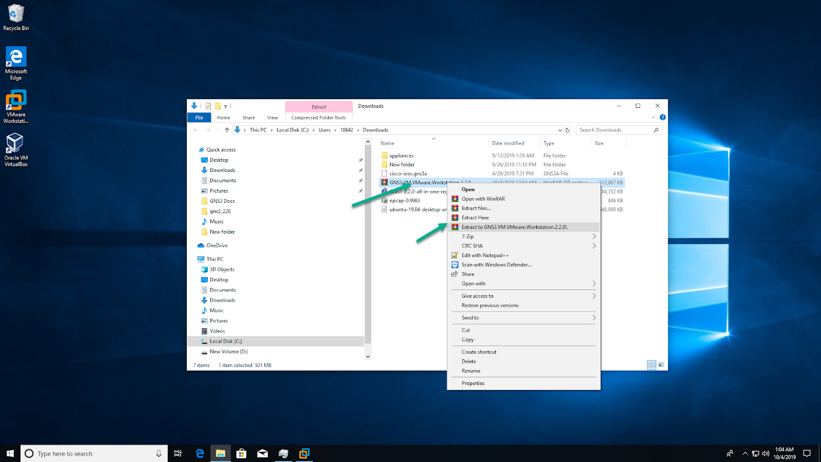
This extracts the “GNS3 VM.ova” file stored within the compressed archive, in order to import it into VMware Workstation.
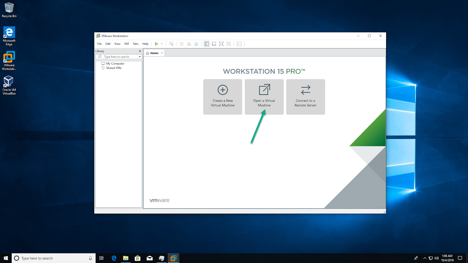
In VMware Workstation, click ‘Open a Virtual Machine’:
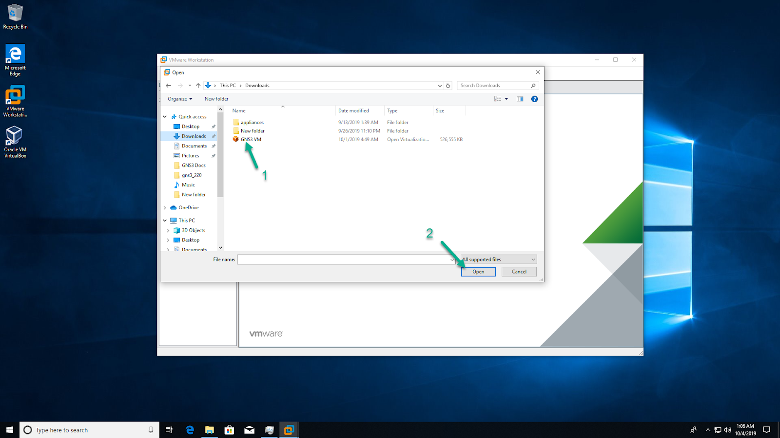
Navigate to the directory where the extracted GNS3 VM.ova is located, and click ‘Open’ to open the OVA Or else we can directly open the GNS3 VM.ova file(by double click) it will redirect to the VMware.
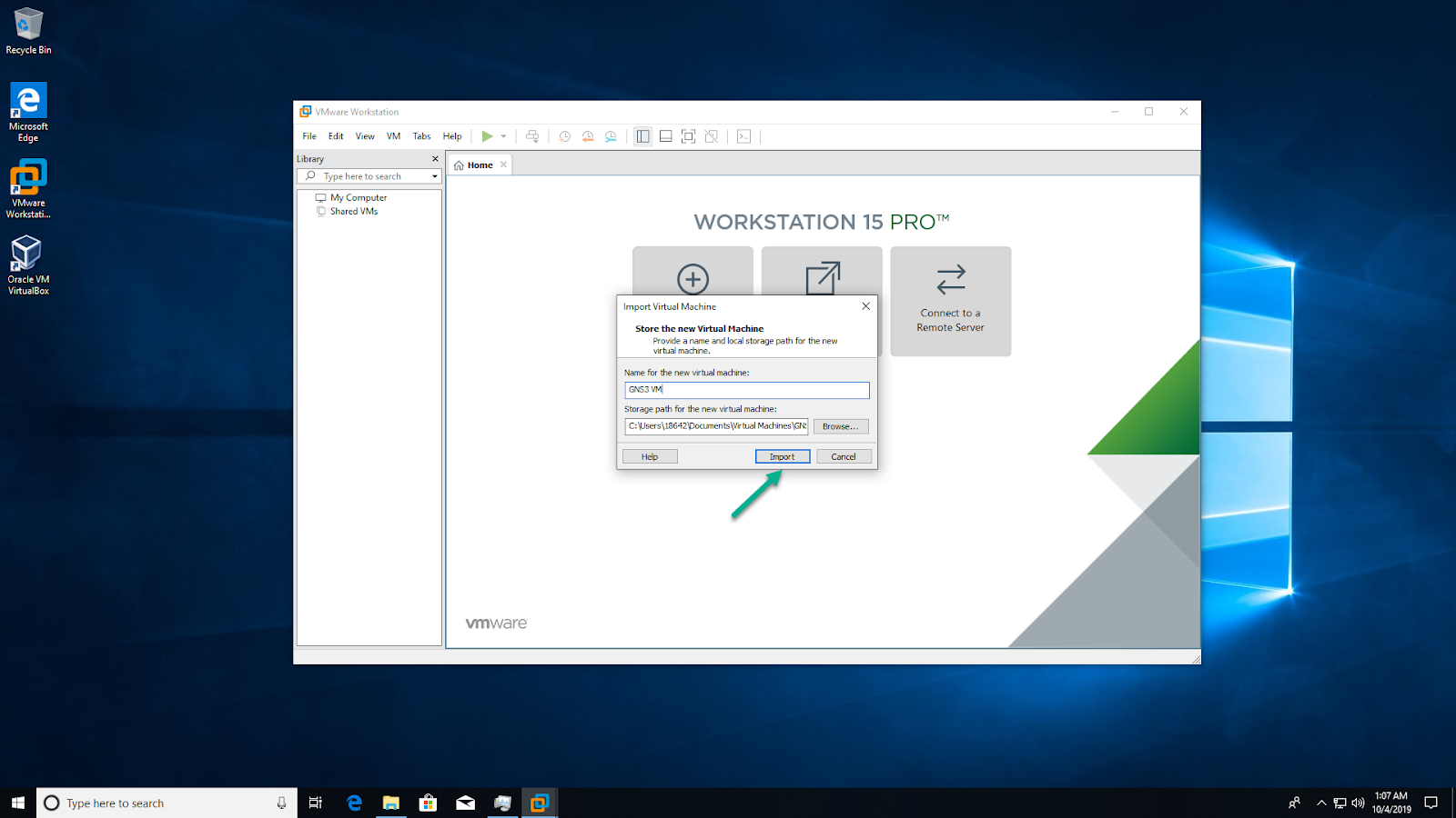
Leave the virtual machine name as ‘GNS3 VM’, and click ‘Import’:
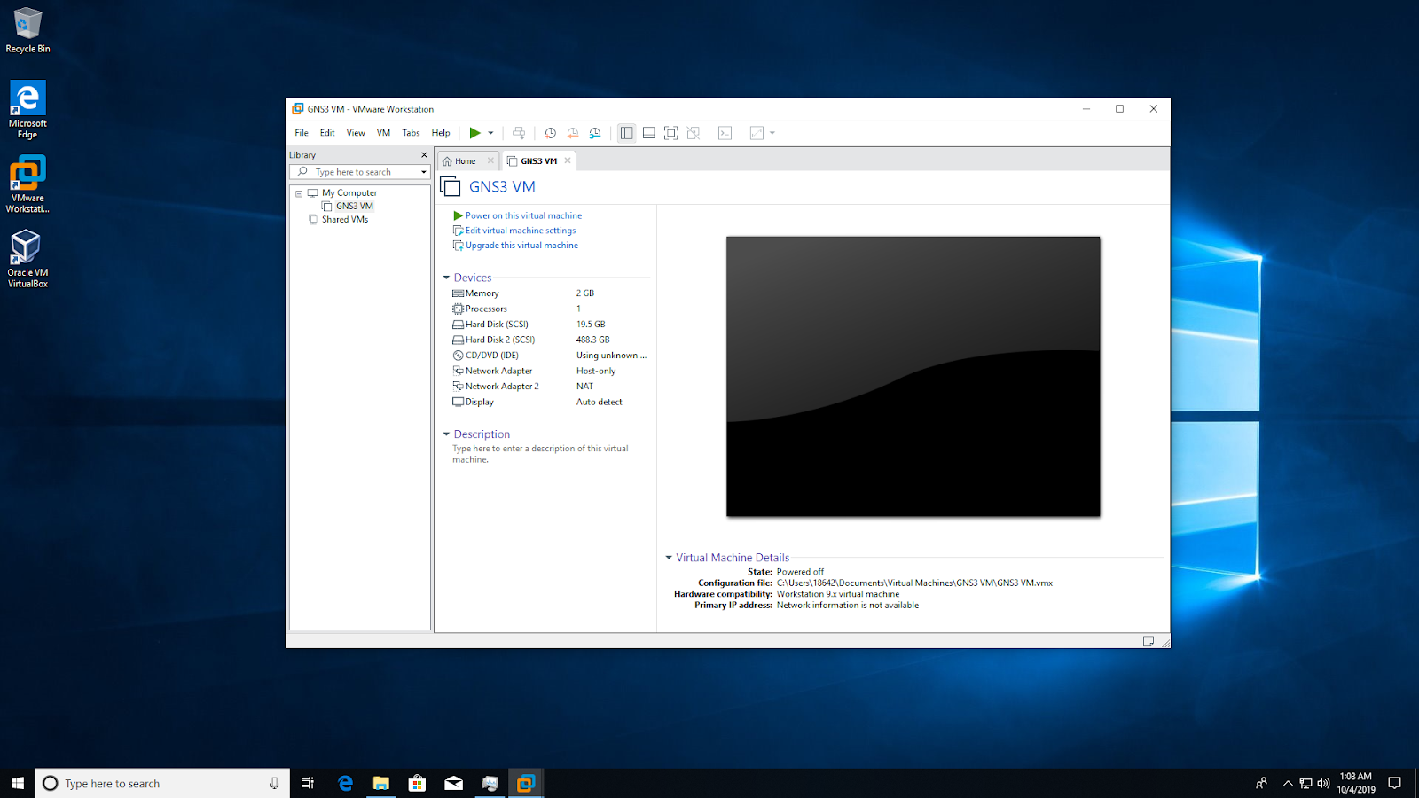
VMware Workstation will import the GNS3 VM:

The GNS3 VM will show as available in VMware Workstation. Leave all settings at their defaults: